
What is 3-axis Machining and Its Applications?
State-of-the-art machined parts can only be persistently produced by employing state-of-the-art tools. It's a simple line of reasoning, one to stick to if a manufacturing company wants to keep an edge in the competitive world of precision engineering. 3-axis machining is a key part of this ethic, and, under most circumstances, the only realistic way to mass produce a part to tight engineering tolerances.
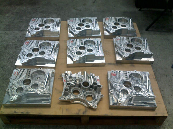
A basic milling and cutting process fabricates parts by shaving or cutting away sections of raw material, rendering the product complete in all its engineered glory. The configuration of the tool employs a multiple axis setup to align the tool head with a stationary part. It's worth noting that the typical configuration is to move the tool while keeping the part stationary on a work surface, but there are models of 3-axis machinery that keep the tool stationary while moving the part. Regardless of the subtle configurations of the machinery, the applied principle remains the same. The tool moves along the X, Y, and Z axis in space, a concept generally represented in the real world as width, length, and depth. Mathematically, the XYZ labels are more practical for machinery, and it's these axial movements that the tool uses. This movement also deserves some clarification. The movement through the three dimensions typically involves two linear channels and the motion of a spindle on the cutting head. This spindle is then the third axis, rising and falling in concert with width and length movements to cut and mill the part. The standard movements across these three established Cartesian planes defines the 3-axis machine, but the addition of a fourth or fifth axis adds rotational capabilities, delivering a flexibility that shares more in common with the human hand and wrist than with a CNC device.
The stages involved in driving a high-end 3-axis device include accurate linear motor movement and direct drive technology capable of interfacing with a computer aided design station. The CAD software translates the 3-D visualization of a part into CNC compatible Cartesian coordinates on the three planes described earlier as X, Y, and Z. The actual tool head could be just about anything, it really depends on the material the part is being cut from, but aluminum, steel, wood, and composites of familiar materials are common parts milled on the 3-axis machine. Thus, a drill, laser, water-cutter, and many other tools mounted at the end of a spindle assembly are standard on the devices. They shift around the material on 3-axis planes to fabricate the object from a raw lump into a final part worthy of being fitted into an automobile or a similarly complex high-end engineering application.
To watch a 3-axis machining process at work is to see a tool accessing detailed spatial data from a digital source. The tool moves simultaneously on all three planes, cutting into raw metal or wood with perfect angular precision, with the spindle descending to provide absolute depth penetration, contouring and finishing the part with repeatable accuracy.
Insights
COPYRIGHT | ABL Engineering
